


|
|
|
|
|
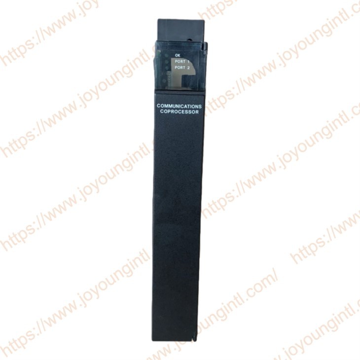
IC697CMM711 |
| IC697CMM711 | |
|
|
|
|
|
|
|
|
30*20*5cm |
|
|
0.5kg |

IC697CMM711 Features
Single-Slot Module
SNP/SNPX Protocol (master, slave)CCM Protocol (master, slave, peer)RTU Modbus Protocol (slave only)Supports connection to MS-DOSe or Windows®programming and configuration software package(monitor only)
12 Mhz, 80C186 Microprocessor RS-422/RS-485 or RS-232 Serial PortsCCM, and SNP/SNP-X. Available on both Ports
Simultaneous Communications on Both Ports(up to 9.6 Kbps, or 19.2 Kbps individually)High Performance Access to PLC Memory
IC697CMM711 Functions
The Communications Coprocessor Module (CMM) is a member of a family of communication modules, and provides both communications control (CCM), remote terminal unit (RTU), and general IC6g*communications(SNP) functionality. CCM, RTU and SNP are aavailable oneon either or both serial ports in any of nine possible configurations:C CM/CCM, CCM/RTU, RTUCCM, RTUU/HU, SNP/SNPSNP/CCM, CCM/SNESNP/RT U ,and RTU/SNP
The CMM provides both the RS-232 and RS-485Interfaces and communicates with the PLC covering the backplane.
Slot: It can be inserted into any slot of the Series 90-70 rack (except Sl,ot 1, where power must be placed).
The relationship with the CPU: The main CPU exchanges "mailbox" data with the CMM711 through the rack backplane bus. The CPU writes the data to be sent to the designated memory area and reads the data received by the CMM711.
Connect to the upper-levelmonitoring systemsn. Asana SNP slave station, communicate with the computer running configuration software such as CIMPLICITY.
Form a Modbus network: As the master station of Modbus RTU, poll multiple slave station devices (frequency converters, meters); Or it can serve as a Modbus RTU slave station for the master station system to read data.
Device integration: Interface with specific serial devices via the user's ASCII protocol.
High-speed communication between PLCS: By connecting with other CMM modules through the CCM protocol, rapid data sharing among PLCS is achieved.
CONFIGURATION is required using the CIMPLICITY CONTROL configurator tool in the Proficy Machine Edition - Logic Developer PLC software (or earlier standalone software Configuration and CONTROL).
Define the module model and the slot where it is located in the hardware configuration.
Assign communication protocols and parameters (baud rate, data bits, stop bits, etc.) to each port.
If it is a Modbus master station, a polling table (defining slave station addresses, function codes, and data address mappings) needs to be configured.
: For standard protocols such as SNP, Modbus, and CCM, the pre-compiled library functions provided by the software are usually used, and users do not need to write complete C programs. Only the ASCII protocol requires users to write specific C program logic.
-
IC697CMM711 communication failure: The PLC is unable to establish a stable communication connection with remote devices such as HMI, remote I/O modules, and other PLCs.
Network configuration error: Such as incorrect IP address configuration, incorrect subnet mask setting, gateway configuration issues, etc.
Communication protocol settings do not match: For example, the protocol configuration between Modbus RTU and Modbus TCP is inconsistent, resulting in an inability to communicate.
Verify the communication settings of IC697CMM711 to ensure that it matches the protocol, IP address, etc., with the external device.
Recheck the communication configuration using GE Fanuc configuration software (such as Proficy Machine Edition) to ensure that the ports and network parameters are correct.
-
-
LED indicator light anomaly: The LED indicator light on IC697CMM711 is showing an abnormality, such as constantly lighting up or not lighting up, indicating that there is a problem with the indicator module.
Power failure: If the power supply is unstable or the voltage is insufficient, the module may fail to start properly, resulting in the indicator light not lighting up or constantly being on. Hardware failure: It could be that there is a malfunction in the internal hardware of the module, causing the LED to fail to display the working status properly.
Check the power supply of the module to ensure it is normal and stable. You can use a multimeter to check the power voltage. If the power supply is normal but the problem persists, consider replacing the IC697CMM711 module to check if it is a hardware fault.